Up next in 10

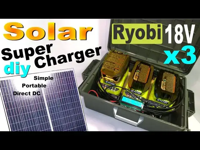
Building a Ryobi 18V Solar Super Charger x3 #DIY battery SuperCharger - simple, flexible & portable!
May 9, 2024

Build your own DIY Solar Powered Ryobi SuperCharger! In this video I show how to put together a simple and effective DIY solar charging solution for Ryobi 18V power tool batteries. It uses direct DC solar electric power to do the work. This is a great setup for off electrical grid field work and remote job sites. I designed this charger to be relatively simple, using common off the shelf parts and it is straightforward to operate. This DIY supercharger is very much plug and play. Hook up the solar panels, plug in 3 batteries, away it goes. As long as there is plenty of sun, batteries will charge all day for free.
Cordless tools with Lithium Ion batteries have changed the face of DIY over the past few years. There is nothing more portable and convenient than cordless power tools. But usually the chargers are lacking in this department, tethered to an AC grid connection. This means dragging a top heavy and complex AC power solution along to charge tools on the go. I am a fan of operating appliances directly from PV solar panels - with little to nothing in between. This DIY 18v supercharger can directly accept a DC input from solar panels or even a 12v car battery if required. This gives flexibility and options. No inverter is required - charge controller and battery bank also can become optional.
The DC converters used are CC CV buck boost converters. They allow operation from a wide variety of DC power sources. Plus they are relatively cheap and simple, and actually could be repaired with basic electronics knowledge. This setup can eliminate complex inverters, charge controllers and heavy batteries, reducing cost and increasing efficiency. From a preparedness standpoint, it makes a lot of sense. When the grid goes down, you can keep charging and keep working!
In this video I will show the build steps required to build this charger and also spend a lot of time explaining how to use DC DC converters in an application like this with solar power. Hope you enjoy the video!
///PARTS LIST - Work in Progress (Scroll down to see)
----------------------------------------------------------------------
🟢 Original Ryobi 18v Solar Charger - Compact Design
https://youtu.be/wPjc8KXD4sw
https://youtu.be/MRazwnwvczg
https://youtu.be/RMJFVHCNw_s
----------------------------------------------------------------------
🟢 My Ryobi 18V Playlist
https://www.youtube.com/playlist?list=PL8a6nRTNyF9OpkM27cgoLVxtfeNBLMpZR
----------------------------------------------------------------------
Check out our blog - Solar Thoughts Blog! https://solarpoweredge.com/
Show More Show Less View Video Transcript
0:00
Hi folks, in this video I document how I built my own flexible solar power DIY 3 port 18 volt Ryubi Supercharger
0:06
And let's get it up to about 21.5 volt. Each of these supplies..
0:30
Hi, folks, Dave here. you how to build a three-port direct DC solar charger for Ryubi 18-volt batteries. The idea scales
1:05
up well even a 4-8-port charger would be possible. I chose three for this project. A pair of 100-watt
1:11
solar panels powers the charger all day for free. No DC to AC inverter is required. There are minimal
1:17
electronic components and the DC converters are fairly simple, cheap, possible to repair if needed
1:22
and very flexible. By lowering the power settings, it could certainly function on a single 100-watt solar panel
1:27
For this project I am again using the Ryobi PCG-002 battery charger because it is readily available
1:33
It also accepts a DC input supply. This is the same charger I used in my last Ryubi solar charger project
1:39
One of the goals of this project is to demonstrate the viability of what I call PV to load
1:44
The concept of attaching useful devices and appliances directly to the PV solar array
1:49
Cutting out the battery, charge controller and inverter could reduce costs and increase efficiency
1:53
In this simple diagram you can see that the idea is to load
1:57
the charge controller of the battery and the inverter and use only a solar panel to do the work
2:01
Of course you could eliminate only the inverter and keep the charge controller in the batteries
2:05
A lot of my DIY prototypes and projects are intended to run off of solar panels directly
2:10
such as this small oven here, linked in the description. The charger can still accept a standard 12 to 48 volt input from a battery bank if needed
2:17
The first part of this video shows the build steps I use to build this charger
2:21
and the second part is a technical explanation of using DC to DC converters in an application like this with solar power
2:26
solar power and I'll include some clips of the charger in operation if you
2:31
like this video please let me know and leave a thumbs up thanks for watching
2:56
I'm going to be a little bit of I'm going to make
3:02
it to be a one I'm going to make it to be the
3:11
I'm going to make a I'm going to be able to be
3:45
Hi. I'm not I'm
4:19
a lot of I'm a lot I'm I'm know
4:45
Thank you. You know
5:45
The The
6:45
I I You know
7:16
and then the I'm not a lot of I'm going to be
7:48
I'm The
8:48
In order to run this charger off of solar panels, I'm going to need three separate batteries. I'm going to need three separate decedc converters. I'm going to explain why that is
9:18
I'll just draw the sun here and we'll put some solar panels here
9:26
Let's assume they're putting out about 40 volts DC. Let's assume they're in series and let's draw them like this
9:37
We have 40 volts DC, sun's shining and we want to drive 3 18 volt chargers using this power supply
9:45
This power supply could vary in voltage. It might be 50 volts. it might be 30 volts, and we have to make sure that the voltage is stable and powers the chargers
9:54
In order to do that, it's going to require three DC converters. If I start with just one DC converter, let's go ahead and just draw one here
10:02
And let's just assume that that 40 volts is going into the DC converter
10:07
And you're getting 18 volts here. In addition of that, I've set it to 2 amps constant current
10:13
and that's to protect the charger, protect the battery, and basically to make sure that there's no safety problems
10:19
And you have your Ryobi B battery, which is right here. Let's just go ahead and draw it
10:24
And the DC converter is charging it through the charger, of course, and everything's fine
10:29
But what if you wanted to charge two batteries, or maybe three, or possibly even four batteries, from the same solar panels
10:35
You might think that all you have to do is just take your DC converter here
10:41
and attach it to a second charger. But that's actually not going to work
10:47
The reason is that this supply, which is really going to be more like 22 volts or so
10:52
the charger is going to pull this DC converter down to whatever voltage it's at
10:56
So let's say, for example, this battery here is deeply discharged and it's 15 volts
11:03
What's going to happen is this battery at 15 volts is going to pull this DC converter
11:07
down to about 15 volts. So you're going to be operating at this voltage right here while the battery slowly charges up
11:12
It's going to start slowly rising up, but it's going to take a while. If I try to attach another charger here, and let's say I put in a battery
11:20
and let's just go ahead and draw the battery, and let's say that it was at 20 and a half
11:26
volts. So now we have a second battery we want to charge. But this voltage supply has been
11:33
pulled down to 15 volts. This DC converter is supplying about 15 volts at 2 amps, and this
11:37
voltage is slowly rising, but it's nowhere near 20.5 volts. What's going to happen is when I connect
11:42
this nearly full battery to a second charger, If I tie it into this DC converter here, it won't charge
11:51
Because 15 volts isn't going to charge a battery that's at 20.5 volts
11:55
And this DC converter is busy right now putting out 15 volts and powering this charger
12:00
It's putting out about 2 amps. It's a constant current supply, which is ensuring that it only puts out 2 amps
12:05
And in order to only put out 2 amps, it has to drop to 15 volts. That's just how it works
12:09
Therefore, I can't attach my second or third battery to the same DC converter. It isn't going to work
12:14
But what will work is if I take another DC converter and I tie that in the same solar panels
12:26
And I've got another 18 volt supply here, two amps. It's the same as this one
12:31
And now it can serve this charger and it can put out about 20 and a half volts at two amps
12:37
And this idea scales up really well. If I want to, I can go ahead and add a third DC converter
12:43
And I can go ahead and tie that in to the solar panels like so
12:47
And now I've got 3 DC converters and three separate supplies in operation here
12:52
And I can charge three separate batteries. And it doesn't matter now what the voltages are
12:59
because each of these supplies here will regulate to whatever that voltage needs to be at
13:03
to charge the battery that's connected. If it's a different one here or here, it won't matter
13:08
The downside is you need three times the converters. However, you're charging three batteries simultaneously
13:12
from only one set of solar panels. Therefore, this kind of a configuration is actually quite useful and actually makes a lot of sense
13:19
What we're going to end up with here is three regulated outputs and three separate chargers charging three different batteries
13:25
all from one set of solar panels or even a single solar panel if you use one that's big enough
13:29
All of these DC converters that I'm going to be using, they look like this
13:35
are DC to DC converters with constant current and constant voltage Now to explain how that works this DC converter can take a DC input voltage
13:49
and it can output whatever you set it to. So for example, I could put in 35 volts on this side
13:54
and I can get 21 volts on this side, whatever I set it to
13:58
I could put whole volts in here and get 21 volts here. I would still get the same voltage because this converter is actually a buck converter
14:05
and it's a boost convert. To explain the difference, a buck converter
14:14
drops the voltage. And it's always going to drop the voltage. You can't do anything else
14:19
And that's actually very useful. This converter here is actually a buck converter
14:26
However, there's also a boost converter. And a boost converter is actually also extremely useful
14:31
because it can raise the voltage. So a boost converter raises the voltage voltage and a buck converter lowers the voltage. This converter does both, so it actually
14:40
has both capabilities built in. What this effectively means is your input voltage, which
14:46
is going to be on these terminals, can be anything. It could be 12 volts, 10 volts, 50 volts
14:52
this particular one can accept as much as 50 to 60 volts, and on the output you can continue
14:57
to have whatever you want. You can have 18 volts or whatever you set it to. In the case
15:00
of a Ryubi battery charger, it needs to be about 21.5 volts, 22
15:04
2 volts or something like that. So this board here is actually a known as a boost buck
15:10
converter or buck boost converter because it does both. It's got both sets of circuits on there
15:14
and it means that you can now disconnect the output from the input in terms of voltage. You can
15:20
use any voltage you want and still get the same results on the output. All of that is within
15:24
reason though. It's not possible to get power out of thin air here. This thing is just going to
15:28
take what it has and work with what it has. It's going to waste a certain amount of that power, maybe 5% in doing this conversion, but it's not possible
15:34
It's very useful because it can do what's called impedance matching, so it can match the impedance of your output to the load that you're running
15:41
A battery has very low impedance usually, and a solar panel would have relatively high internal resistance or impedance
15:47
and so you would waste power by just attaching the solar panel straight through
15:51
In addition to that, it would not be possible to charge three separate sets of battery with just one solar panel if you want to do that efficiently
15:57
This is a more efficient solution overall if you take everything into account
16:04
Now I'm going to show you how to set these power supplies up. It doesn't matter which one you use. This is just the one that I prefer to use
16:10
I've used it a number of projects and I like them. These boards are actually sold as LED drivers but they can do other things as well
16:19
It has another feature built in. As you can see, it has two trim pots on it
16:23
One is for voltage and one is for current. I'll go over that more later in the video
16:31
Constant current. What is constant current? This board also has the feature of constant current and constant voltage
16:41
So constant voltage just means that you set the voltage to what you want, and it will try to maintain that voltage no matter what you put on the input
16:49
This board also has what's called constant current. Constant current is extremely useful because it allows you to control how much power flows through this board no matter what
17:00
As you know, voltage times current or amps is watts. What we're going to do is we're going to set the constant voltage on this board to about 21 and a half volts
17:11
However, there's a problem. If I put two big 100 watt solar panels on this board
17:15
potentially I could have a problem with this board burning out or I could harm the battery
17:19
I could cause a fire, who knows what would happen. This board not only limits the voltage, but it has constant current, which means it could control the current as well
17:29
And I'm going to set mine to around 2 or 3 amps. So how does a constant current board respond to a condition where it needs to limit the current
17:37
The answer is when the current starts to get too high, it will drop the voltage to reduce the current
17:42
In early days of testing this charger, 2 amps is good enough, so we'll make it 2 amps
17:48
And that's going to be right around 40 watts, which is certainly a nice charge into the battery
17:53
It's not super fast, but it can be made faster. I'm going to err on the side of caution, and I'm going to program my boards to be 2 amps
18:00
and later on I can put them up to 3 or 4 amps if I choose to. it's not a problem. You can recognize this board as having both features because usually
18:07
there will be two trim pots, one for voltage and one for current. And I will show you how to
18:12
adjust these boards to put out the right amount of current and voltage. Let's briefly
18:15
review the difference between a buck converter and a boost converter. This board is
18:19
actually both. A buck converter could take, let's say, a 24 volt source and convert it to 12
18:24
volts DC. And you could run a 12 volt load off of a 24 volt power supply by using a buck
18:29
converter, which always drops the voltage. But a boost converter, for example, could take a 12
18:34
volt battery and boost it up to 24 volts, and you could run a 24-volt load from a 12-volt battery
18:39
A boost buck converter, which is what this is, has both capabilities built in. It's a little
18:44
more complicated, but it's extremely useful with solar power. You may use different solar panels
18:49
the conditions may change. You never know what the voltage supply will be. This board can both
18:52
raise and lower the voltage independent of the input, and that's why I chose this board for the
18:57
project. In order to get this board working properly, I need to set it to the proper
19:01
voltage on the output as well as the proper current. How do I do that? Well, I'm going to
19:05
show you right now how to do that. In order to test this board, this is a brand new
19:12
board that I just got. I need to go ahead and hook it up to a power supply, and I want to set
19:17
the voltage output in the current. So let's go ahead and do that. All right, first step is
19:23
going to be to power up this board using my bench power supply, or you can use a solar panel. I
19:27
use a solar panel but today I'm just going to use the bench power supply because that's more convenient I'm going to go ahead and make sure the
19:33
output wires are not shorted I'm gonna take the bench power supply connect the
19:38
positive and negative and it powers up you can see the blue light which is
19:44
illuminated on the board that means it's turned on now let's find out what this board is set to in terms of output voltage I'm not gonna connect a load to it
19:50
yet I've got my multimeter in the upper left-hand corner connected to these
19:55
clips and I'm going to go ahead and measure the output. And you can see I'm getting
20:01
24 volts. So this was set from the factory at 24 volts. It's a brand new board. 24
20:06
volts is not the correct voltage for my project so I'm going to go ahead and adjust that. Now we need to identify how to adjust the voltage and it's very
20:15
clearly labeled in the board CV. You see the letters there where I'm pointing and
20:18
there's a little arrow going around the corner and that's pointing at this trim
20:22
pot here. That's actually the constant voltage supply adjustment. For constant current there actually two letters CC which is right where I pointing and that has actually got a little arrow pointing at this trim pot here which tells me that this bottom one adjusts the current I not going to touch the current yet I
20:40
going to go ahead and change the voltage to be whatever I want it to be. In this case for the Ryubi supercharger project I want to use about 21 and a half volts. I'm
20:49
going to go ahead and change the trim pot here to correct the voltage to 21.5
20:54
volts instead of 24. Let's go ahead and do that. Now in order to change the voltage. Generally speaking I found that you have to turn it clockwise to
21:01
get less voltage. So I'm just going to go ahead and turn this clockwise and indeed
21:07
the voltage drops. Let's now turn it to the left which is counterclockwise and let's
21:14
get it up to about 21 and a half volts. It only takes a little bit of turn on the trim
21:19
pot to get a change. You have to be very precise. Yeah it's close and I managed to get
21:27
it pretty close to 21.5 volts by adjusting the trim pot very carefully and that part is done
21:33
The next thing I want to do is I want to adjust the spore to 21 and a half volts and also I want to
21:38
put out two amps. How do I do that? Well I'll show you how I do it. There's probably other ways
21:42
to go about this but I'll show you my tried and true method that I've used for years. I'm going to
21:47
turn the trim pot to adjust current all the way to the right until the board stops putting out
21:52
voltage and that's going to tell me I've hit the lower limit. So let me go ahead and do that. I'm going to keep turning the current adjustment trim pot to the right a little bit at a time until I see the voltage drop on the output
22:04
And it just dropped. That means I've hit the minimum current. Now I'm going to turn it to the left, about a half a turn, and it goes back up to 21 volts
22:14
So the current is effectively set to pretty much the minimum right now. And what I need to do is put a load on this and adjust the correct current level
22:22
What I'm going to do is I'm going to take this resistor here, it's a power resistor and an amp meter
22:28
and I'm going to put that across the output and use it to basically set the current to the value that I want
22:33
Okay, I have my trusty GE-2524 multimeter here. I love these meters because when you turn them on, they stay on until the battery runs down
22:39
They don't beep. They're not smart meters. They just do a good job when they work
22:44
If you're interested, I have two great videos linked in description about using a digital multimeter with solar power
22:49
It covers an extremely broad variety of DIY and entry-level topics, as well as intermediate and somewhat advanced topics
22:56
There's two separate videos. One is using the GoChi Fix Smart Digital Multimeter, which is over here on the left
23:01
And the other video, which is also very good, is using this GE Multimeter, a very basic meter that does a really good job
23:06
I really highly recommend you watch both of those videos if you want to learn about using a digital multimeter
23:11
and you want to expand your knowledge and skill sets. First thing I'm going to do is I'm going to take this multimeter here, and I'm going to set it to the 10-amp range
23:17
I'm going to wait for it to zero. It takes a while in this meter
23:23
There it goes. Now that it's zeroed, I'm going to take the red lead out of the socket for volts
23:31
oms, and milliamp, and I'm going to put it in the 10-amp location. It's important to remember that this is a short circuit through the meter
23:38
As soon as you're done measuring current, you need to take this out and put it back in the volts socket
23:43
And that's covered in my video about how to use a digital multimeter. and I actually use one of these very meters to make that video
23:51
All right, let's go ahead and measure current using this meter. You can handle up to 10 amps, that should be enough
23:58
What I'm going to do is I'm going to take the connections on this meter
24:02
Those are right here, and I'm going to connect a power resistor to it
24:08
So I've got a power resistor on one lead, and I've got the other lead here
24:13
And I'm going to attach that to the output, which is right here, and I'm going to see how much current I get
24:18
Now this is kind of a short circuit, but it's not a short circuit. It's got a resistor, this resistor right here
24:24
And so I like doing it this way instead of just shorting it out with a pair of wires
24:28
I like a little bit of resistance in there in case something goes wrong. All right, let's go ahead and take this resistor and this amp meter
24:33
and let's place it across the terminals, positive and negative, and see what happens. All right, you can see the output voltage collapse and I got like 30mmm
24:40
So obviously the current is way too low. So let's go ahead and raise that. Now, in order to get this board to supply the current I'm looking for, I had to raise the
24:48
input voltage to about 29 volts, and I'm not surprised by that or terribly concerned about it
24:53
Some of these boards simply cannot provide the current through a resistor like this when you're attempting to adjust them
24:57
I'm not too concerned about it. I wouldn't normally just short a resistor across the output anyway
25:02
I just want to check the current and make sure it's set properly for my application. Let me go ahead and turn the trim pod on the current, and I'm going to connect the resistor
25:12
You can see I'm getting about 60 millie amps. I'm going to turn it to the left a little bit
25:18
Now I'm up to 300mmphs. I'm going to go a little bit higher than that
25:29
I want two amps. It's actually hard to adjust the current because it's very sensitive
25:34
The slightest turn changes the value. So I'm going to try to hit two amps here
25:42
There's two amps. I'm going to disconnect the resistor. You can see that it was putting out two amps
25:46
All right, I have this board set to 21 and a half volts and about two amps of current, and it's ready to go ahead and be used in the project
25:56
I took this charger outside in my yard for its maiden test. I configured it to work with two of my favorite solar panels I used for outdoor applications. They're 100 watts
26:04
I found this Ryubi charger to be very lightweight and easy to carry. With a DC converter set at a relatively mild power setting, I was able to hit 136
26:12
into three of my Ryubi 18 volt batteries. The fans did a good job and I should be able to get more power through this setup if I want to
26:35
One of the things I like about this setup is that the DCDC converters are tunable and you can set them to any power output that you want, even having three different power level
26:42
and that allows you to configure and customize how you charge your batteries and what kind of solar panels you use on a daily basis
26:49
This setup turned out to be pretty much plug-in play. I just put my solar panels up, plug them in, put the batteries in, and off they go
26:56
As long as the sun is shining, I can charge three batteries. If the sun gets a bit dim, sometimes I'm limited to only two or only one battery, but that's to be expected
27:04
Please leave a thumbs up if you enjoyed this project. Thanks for watching, and hope to see you next time
27:12
Thank you
#Electronics & Electrical
#Power Supplies
#Construction & Power Tools
#How-To, DIY & Expert Content